
I got a LED strip with a piece a drawer set and the controller that came with it was dead on arrival. Now, this was a probably $5 – $10 set of LEDs – but I was excited about them and figured this could be a fun project. So I designed a LED controller with two knobs (color and brightness) and used only parts-bin parts. The brightness control pot even has a switch so when turned fully counter-clockwise it turns cuts power entirely. Note: I didn’t add the switch on the diagram.
Transistors are MPSA42 and MPSA13 but could be anything similar as long as they can carry at least a couple hundred ma.
9v DC booster is DFR Robot DFR0952 set to 9v
C1 – 0.1uF
C2 – 2.2uF
R1, R2, R3 – 510ohm
R4, R5, R6, R7 – 10k ohm
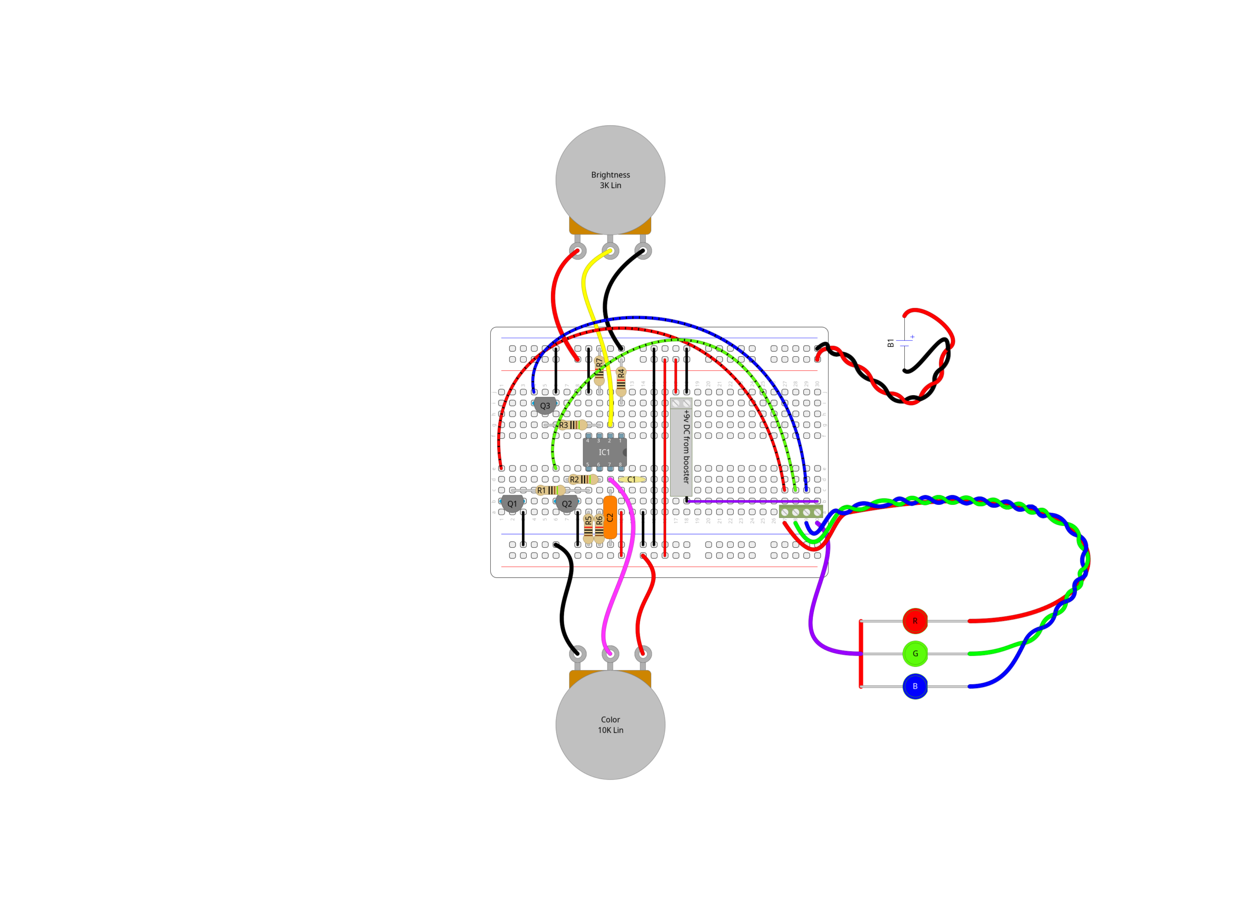
Diagram for ATtiny85 RGB LED controller, designed in DIYLC.
I did all of the coding in Arduino IDE.
int ledR = PB0; // Output ping for red LED pin 5
int ledG = PB1; // Output ping for green LED pin 6
int ledB = PB4; // Output ping for blue LED pin 3
int brightness = A3; // Input pin for brightness potentiometer
int color = A1; // Input pin for color change potentiometer
int colorVal = 0; // Store value of color potentiometer
int brightnessVal = 0; // Store value of brightness potentiometer
int red = 0; // Set default to off
int green = 0; // Set default to off
int blue = 0; // Set default to off
int brightnessOutput = 2; // Set default brightness to 2
void setup() {
// Set led pins to low before setting as output:
digitalWrite(ledR, LOW);
digitalWrite(ledG, LOW);
digitalWrite(ledB, LOW);
// Set led pins to be an output:
pinMode(ledR, OUTPUT);
pinMode(ledG, OUTPUT);
pinMode(ledB, OUTPUT);
// Set inputs as inputs
pinMode(color, INPUT);
pinMode(brightness, INPUT);
}
void loop() {
analogWrite(ledR, ((red * brightnessOutput) / 100) * 1); // Red brightness based on color, brightness, and calibration for white (1 = max full power)
analogWrite(ledG, ((green * brightnessOutput) / 100) * 1); // Green brightness based on color, brightness, and calibration for white (1 = max full power)
analogWrite(ledB, ((blue * brightnessOutput) / 100) * 1); // Blue brightness based on color, brightness, and calibration for white (1 = max full power)
colorVal = analogRead(color); // Read value of color change potentiometer
brightnessVal = analogRead(brightness); // Read value of brightness potentiometer
if (brightnessVal > 1000) { // Top of potentiometer, set to full brightness
brightnessOutput = 100;
} else if (brightnessVal > 25) {
brightnessOutput = brightnessVal / 10; // Calculate level of brightness
} else {
brightnessOutput = 2;
}
// Read colorVal and assign RGB values
if (colorVal > 910) { // Set to white (full RGB) if at top of potentiometer, total of 510 so things stay fairly even
red = 170;
green = 170;
blue = 170;
} else if (colorVal > 895) {
red = 85;
green = 85;
blue = 85;
} else if (colorVal > 750) {
red = 255;
green = 255 - ((colorVal - 750) * 1.7); //ramp green up from 0-255 in the 1000 to 750 zone
blue = 0;
} else if (colorVal > 600) {
red = (colorVal - 600) * 1.7; //ramp red down from 255-0 in the 750 to 600 zone - multiply by 1.7 to get range of 255
green = 255;
blue = 0;
} else if (colorVal > 450) {
red = 0;
green = 255;
blue = 255 - ((colorVal - 450) * 1.7); //ramp blue up from 0-255 in the 600 to 450 zone - multiply by 1.7 to get range of 255
} else if (colorVal > 300) {
red = 0;
green = (colorVal - 300) * 1.7; //ramp green down from 255-0 in the 450 to 300 zone - multiply by 1.7 to get range of 255
blue = 255;
} else if (colorVal > 150) {
red = 255 - ((colorVal - 150) * 1.7); //ramp red up from 0-255 in the 300 to 150 zone - multiply by 1.7 to get range of 255
green = 0;
blue = 255;
} else {
red = 255;
green = 0;
blue = colorVal * 1.7; //ramp blue down from 255-0 in the 150 to 0 zone - multiply by 1.7 to get range of 255
}
}
