
Editor’s note: This post has been over a year in the making (I just kept procrastinating). It’s finally here, time to share some Arduino fun.
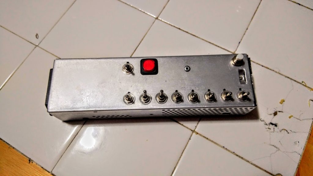
After creating my last metronome, based on a 555 IC, I decided I wanted to up the ante. I wanted to have a metronome that I could accurately control right to the single BPM. I also did not want to have a digital display. The best way I came up with was binary input via 8 toggle switches. This would allow me to control BPM from 0-255 BPM with precise accuracy. The easiest way I could come up with to control this is with an Arduino or Arduino clone. I chose the clone route and picked up an Adafruit Pro Trinket 5v/16mhz for all of $10. I also chose to get a small amplifier board to increase the volume coming off the PWM output of the Arduino. I used a small 8 ohm speaker from a greeting card and mounted the whole contraption in an old Apple LCII PSU I had gutted and saved.
This was my first Arduino project and also my first experience with Fritzing.
Rather than have the code do complex math, I simply had it look to each switch as a binary register and add it’s value if flipped high. IE, the first switch (from right to left) is valued as “1” if high, and “0” if low. While the switch all the way to the left is the 128 bit register and if flipped high is valued at “128”, if flipped low it is valued at “0.” After it checks all registers, it adds them up and there is your calculated BPM from binary.
As far as the physical build goes, I chose to use a 9v battery drawer for easy battery access. I also chose an LED embedded push button switch with separate LED control (normal it is lit when on, this can be controlled separately). I have it light up to match the BPM. When pushed, it still lights, but it mutes the speaker for quiet operation.
And now to the fun bits:
#define SPKR  12      // Speaker pin
 #define LED  13      // LED pin

 void setup(){
   // Configure input pins as an input and enable the internal pull-up resistor
   pinMode(3, INPUT_PULLUP);
   pinMode(4, INPUT_PULLUP);
   pinMode(5, INPUT_PULLUP);
   pinMode(6, INPUT_PULLUP);
   pinMode(8, INPUT_PULLUP);
   pinMode(9, INPUT_PULLUP);
   pinMode(10, INPUT_PULLUP);
   pinMode(11, INPUT_PULLUP);
   pinMode(SPKR, OUTPUT);  // Output to amp/speaker
   pinMode(LED, OUTPUT); // LED
 }

int BPM() {
   int Sum = 0; // Start at 0, add registers if they are flipped high
   if (digitalRead(3) == HIGH)
     Sum += 1;
   if (digitalRead(4) == HIGH)
     Sum += 2;
   if (digitalRead(5) == HIGH)
     Sum += 4;
   if (digitalRead(6) == HIGH)
     Sum += 8;
   if (digitalRead(8) == HIGH)
     Sum += 16;
   if (digitalRead(9) == HIGH)
     Sum += 32;
   if (digitalRead(10) == HIGH)
     Sum += 64;
   if (digitalRead(11) == HIGH)
     Sum += 128;
   return(Sum);
 }

void loop() {
   // Make metronome noises!
     if (BPM() == 0) { // If BPM is set to 0, light LED solid
       digitalWrite(LED, HIGH);
     } else {
       tone(SPKR, 440, 5); // Frequency of tick, length of tick
       digitalWrite(LED, HIGH); // Light LED for the length of the delay below
       delay(100);
       digitalWrite(LED, LOW);
       delay((60000 / BPM()) - 100); // Time between beats in ms, adjusted for above LED delay
      }
 }
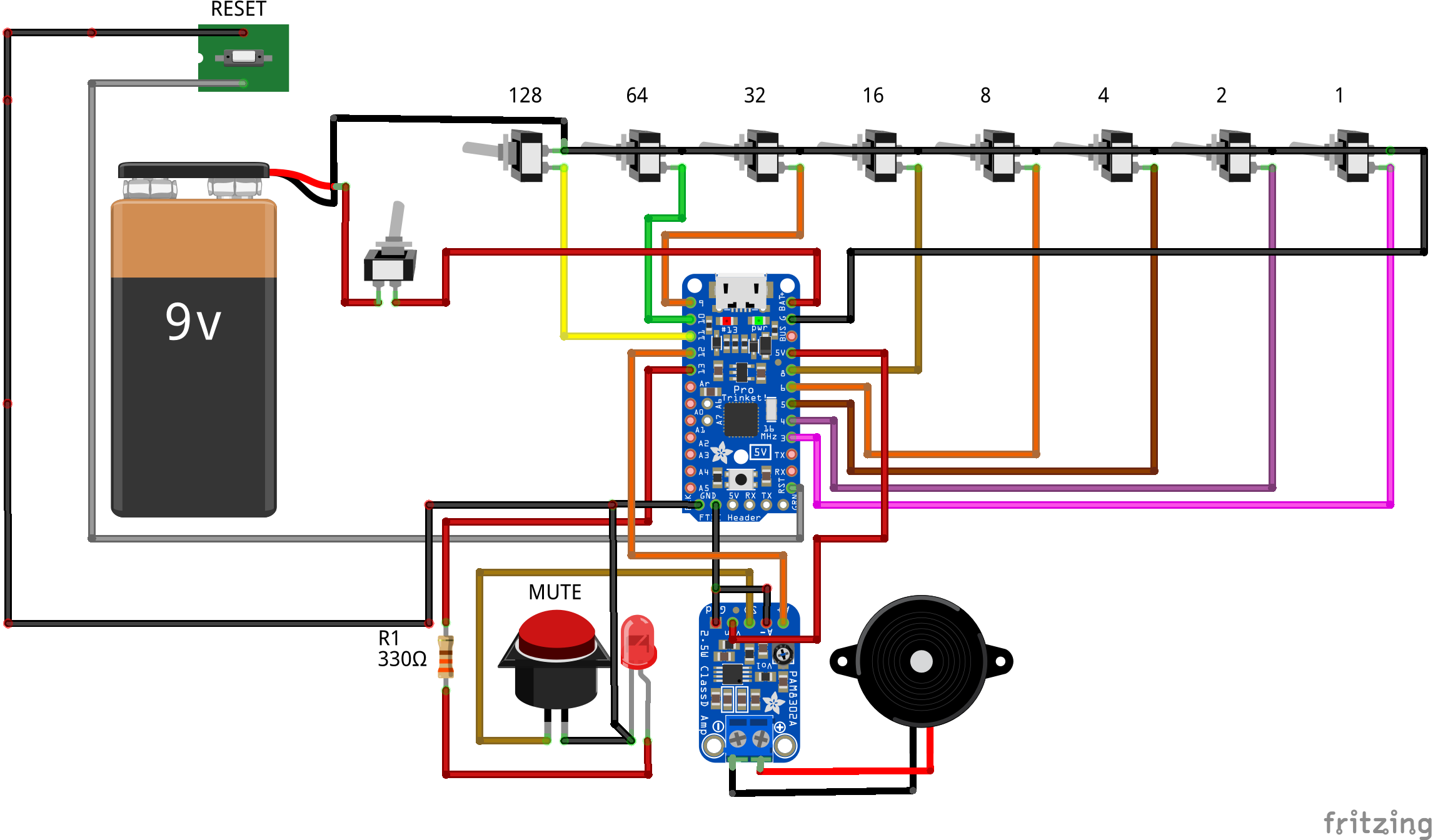
8bit metronome Fritzing diagram
