8bit Metronome

8bit-metronome
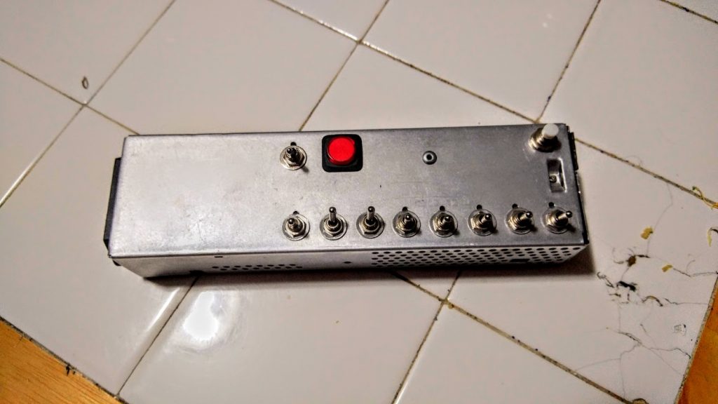
8bit-metronome in Apple LCII PSU enclosure

Editor’s note: This post has been over a year in the making (I just kept procrastinating). It’s finally here, time to share some Arduino fun.

After creating my last metronome, based on a 555 IC, I decided I wanted to up the ante. I wanted to have a metronome that I could accurately control right to the single BPM. I also did not want to have a digital display. The best way I came up with was binary input via 8 toggle switches. This would allow me to control BPM from 0-255 BPM with precise accuracy. The easiest way I could come up with to control this is with an Arduino or Arduino clone. I chose the clone route and picked up an Adafruit Pro Trinket 5v/16mhz for all of $10. I also chose to get a small amplifier board to increase the volume coming off the PWM output of the Arduino. I used a small 8 ohm speaker from a greeting card and mounted the whole contraption in an old Apple LCII PSU I had gutted and saved.

This was my first Arduino project and also my first experience with Fritzing.

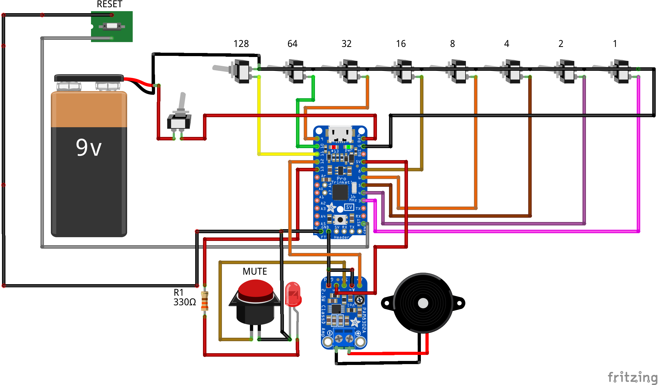
Rather than have the code do complex math, I simply had it look to each switch as a binary register and add it’s value if flipped high. IE, the first switch (from right to left) is valued as “1” if high, and “0” if low. While the switch all the way to the left is the 128 bit register and if flipped high is valued at “128”, if flipped low it is valued at “0.” After it checks all registers, it adds them up and there is your calculated BPM from binary.

As far as the physical build goes, I chose to use a 9v battery drawer for easy battery access. I also chose an LED embedded push button switch with separate LED control (normal it is lit when on, this can be controlled separately). I have it light up to match the BPM. When pushed, it still lights, but it mutes the speaker for quiet operation.

And now to the fun bits:


#define SPKR  12      // Speaker pin
 #define LED  13      // LED pin

 void setup(){
   // Configure input pins as an input and enable the internal pull-up resistor
   pinMode(3, INPUT_PULLUP);
   pinMode(4, INPUT_PULLUP);
   pinMode(5, INPUT_PULLUP);
   pinMode(6, INPUT_PULLUP);
   pinMode(8, INPUT_PULLUP);
   pinMode(9, INPUT_PULLUP);
   pinMode(10, INPUT_PULLUP);
   pinMode(11, INPUT_PULLUP);
   pinMode(SPKR, OUTPUT);  // Output to amp/speaker
   pinMode(LED, OUTPUT); // LED
 } 

int BPM() {
   int Sum = 0; // Start at 0, add registers if they are flipped high
   if (digitalRead(3) == HIGH)
     Sum += 1;
   if (digitalRead(4) == HIGH)
     Sum += 2;
   if (digitalRead(5) == HIGH)
     Sum += 4;
   if (digitalRead(6) == HIGH)
     Sum += 8;
   if (digitalRead(8) == HIGH)
     Sum += 16;
   if (digitalRead(9) == HIGH)
     Sum += 32;
   if (digitalRead(10) == HIGH)
     Sum += 64;
   if (digitalRead(11) == HIGH)
     Sum += 128;
   return(Sum);
 } 

void loop() {
   // Make metronome noises!
     if (BPM() == 0) { // If BPM is set to 0, light LED solid
       digitalWrite(LED, HIGH);
     } else {
       tone(SPKR, 440, 5); // Frequency of tick, length of tick
       digitalWrite(LED, HIGH); // Light LED for the length of the delay below
       delay(100);
       digitalWrite(LED, LOW);
       delay((60000 / BPM()) - 100); // Time between beats in ms, adjusted for above LED delay
      }
 }

8bit metronome Fritzing diagram

Posted in Circuits and Electronics, Hobbies, Music, Upgrade | Comments Off on 8bit Metronome

Copper pipe guitar wall hanger

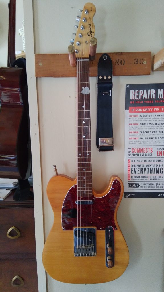
I’ve finally made a wall hanger for my telecaster.  Everything was scrap from other projects.  The wood came from the underside of a dresser that got taken apart, the copper is from old baseboard, the wooden “plugs” in the copper are from something years ago (honestly, I forgot I even had this in the basement).  The “feet” on the lower pieces were from an old parts CB radio I took apart years ago.

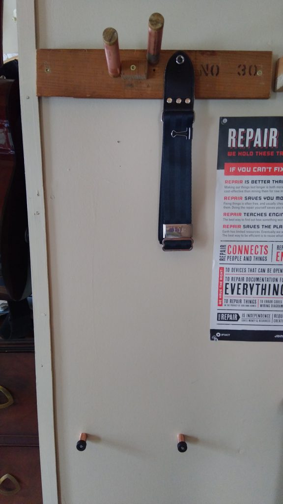
The hanger itself consists of a board with two pieces of 3/4″ copper held in place by 3/4″ dowel whittled down to fit tightly in the pipe.  These pieces of dowel then got cut at roughly a 15 degree angle and screwed to the board.  This makes the copper pipe mounts slope upward, holding the guitar securely.  The copper pipes slip over these and then I put two similar pieces of dowel (cut straight this time) in the top of the pipes to make caps.  These caps protect my guitar from nicks and scratches while loading it into the hanger.

The two lower legs are to keep the guitar from trying to rotate while hung on the wall.  The guitar just barely touches them when it is in the hanger.  These pieces are 1/2″ copper pipe and have plastic “feet” sitting on top with long screws going through them that mount them to the wall.

It works great and I love the look.

Telecaster hanging in it’s new home.
Telecaster removed to show copper pipe pieces used as hanger.
Posted in Hobbies, Home and Homestead, Music | Comments Off on Copper pipe guitar wall hanger

True bypass with DPDT and LED indicator

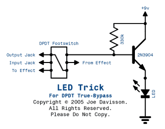
Typically to get true bypass with an indicator LED, you need a 3PDT.  Sometimes these are hard to source, and even when found, quality can be less than perfect.  To get around this you can use relays to control switching of your circuit, or you can use Joe Davidson’s LED trick.  I’ve used this successfully and really love the simplicity and the fact that I can use parts I typically have on hand already as well.

Joe Davidson's LED trick

Joe Davidson’s LED trick allows for using a SPDT switch, LED indicator, and still maintaining true bypass.

Posted in Circuits and Electronics, Music | Comments Off on True bypass with DPDT and LED indicator

Simple guitar cable tester

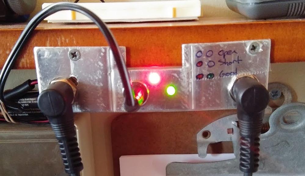
With social distancing being the current norm, I’m working primarily from home right now.  As such, I found I needed to clean my work area.  Doing this, I also found I had a lot of random bits around and decided to make something of them.  Here is a simple cable tester I’ve made based on ideas found at diystompboxes.com.  I shared the idea and more photos on SSGuitar.com, but here is the short version:

Simple guitar cable tester

Note: I chose to omit the speaker and subbed R1 with a 1k to reduce brightness.


Good cable!

No lights on means the cable is electrically open.  Just the red LED on means there is a short.  Both lights means you are in business!


Posted in Circuits and Electronics, Hobbies, Music | Comments Off on Simple guitar cable tester

Raspberry Pi Digital Signage

There have been many different attempts at inexpensive digital signage over the years.  My favorite, one that I use regularly where I work, is Raspberry Pi for digital signage.  Put simply, I set up a Raspberry Pi to load a continuous loop of a Google Slideshow.  This refreshes once every 15 minutes to load new content.

Here’s how we do it.

First, run all updates on your new Pi. (sudo apt-get update, sudo apt-get upgrade).  I like to also run sudo apt-get dist-upgrade and sudo autoremove to fully upgrade plus clean things up.

Next, install clutter and automation (sudo apt-get install clutter and sudo apt-get install automation).

Set your auto config to keep the Pi from going to screensaver as well as load the slideshow automatically on boot.  The file you need to edit is /etc/xdg/lxsession/LXDE-pi/autostart.  You’ll want it to look like this:

@lxpanel –profile LXDE-pi
@pcmanfm –desktop –profile LXDE-pi
point-rpi
@xset s off
@xset -dpms
@xset s noblank
chromium-browser –noerrdialogs –disable-infobars –incognito –kiosk http://web.address.com

Now edit crontab to refresh every 15 minutes (crontab -e):

#Refresh every 15 minutes
*/15 * * * * xte “key F5” -x:0

That’s it!  Enjoy your new digital signage!

Posted in Computers and Hardware, Technology | Comments Off on Raspberry Pi Digital Signage