It seems a popular thing to put additional lights onto SCX24’s of all flavors (C10, Deadbolt, Wrangler, Gladiator, and now the Bronco). Interestingly though, no one seems to want to share information for how to add functioning brake lights and reverse lights. I’ve created a pinout after putting tail lights, brake lights, and reverse lights on my C10. Please do keep in mind that this is for the Axial AE-6 ESC/RX and may not be compatible with the newer SCX24’s that use different electronics.
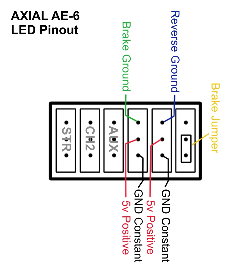
Axial AE-6 LED Pinout for tail lights, brake lights, and reverse lights.
Note: To do the tail and brakelights as combination units with the same LED, I use a larger resistor to allow through about 5ma per LED for tail lights. Then the brake controller turns on and sends a parallel charge to the LEDs giving an additional 15ma per LED. You can sort this out by using a parallel resistor calculator and making sure that your two resistors together in parallel do no exceed the value you were looking for as a maximum for the LED you chose.